What is Lift Off Distance Mouse? Master Your Sensor for Peak Accuracy
Mainstream tech blogs obsess over arbitrary peripheral numbers. They regurgitate marketing material pushing 42,000 DPI sensors and 8,000Hz polling rates while ignoring the single most impactful metric in competitive hardware geometry: the Z-axis.
Asking exactly what is lift-off distance mouse technology actually means, peeling back the layers of optical physics to understand why aiming feels either surgically precise or violently inconsistent. The harsh truth is that raw processing speed means nothing if the optical navigation engine cannot intelligently determine when the chassis leaves the tracking surface.
Hardware manufacturers often hide the physical limitations of their optical assemblies behind proprietary software sliders. This exhaustive analysis bypasses the marketing fluff to deconstruct the exact sensor mechanics, firmware logic, and material science governing mouse tracking. The objective is to map the physical disconnect between the sensor lens and the mouse pad.
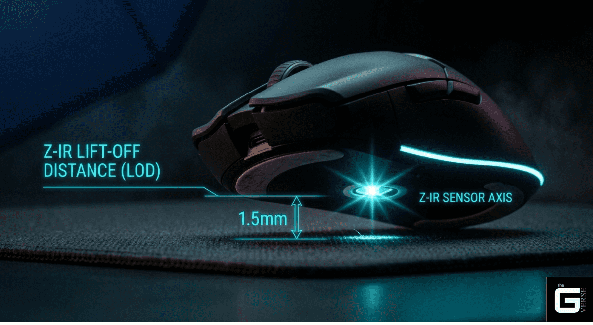
The Basics of LOD: Lift-Off Distance (LOD) is simply how high you must lift your mouse before it stops moving the cursor on your screen (the precise vertical Z-axis threshold at which an optical peripheral’s sensor halts translation of surface data).
The Goal: Adjusting this height perfectly prevents your cursor from wandering, jumping, or lagging when you pick up and reposition the mouse (eliminating spatial drift and temporal tracking stutters).
The Moving Parts: This behavior is controlled by how fast the mouse’s internal camera takes pictures (CMOS frame rates), how your mousepad bends light (surface refractive indices), and the mouse’s internal software rules for cutting off tracking (firmware-level Asymmetric Cut-off protocols).
The Science of Speed: This analysis breaks down the physical parts (hardware mechanics), light behaviors (optical physics), and surface materials (material science) required to achieve instant, lag-free mouse tracking (zero-latency mouse telemetry) for professional use.
Understanding What Is Lift Off Distance Mouse Technology
The mouse lod dictates the exact vertical threshold at which the internal optical sensor stops translating surface data into cursor movement. When a peripheral is raised from the desk, the internal Digital Signal Processor (DSP) must instantly sever the sensor tracking feed. Failing to cut this feed results in the sensor interpreting the diagonal arc of the lift as lateral movement, pulling the crosshair off target.
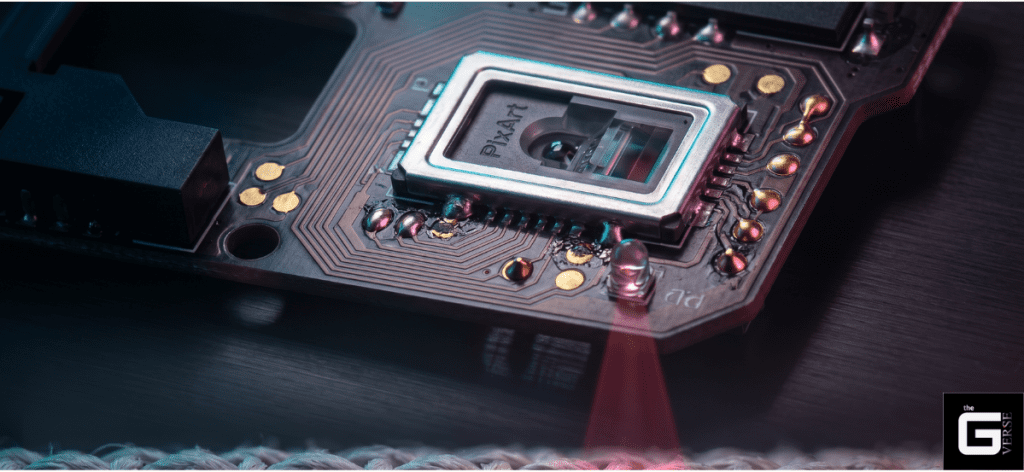
Modern optical mice do not physically “feel” the mat. They operate as hyper-fast CMOS cameras. A light-emitting diode (LED) or infrared laser illuminates the microscopic fibers of the surface. The sensor captures tens of thousands of image frames per second up to 20,000 FPS on flagship silicon like the PixArt PAW3950MAX.
By running rapid cross-correlation algorithms on these sequential frames, the DSP calculates the X and Y displacement deltas. The mouse lift-off distance acts as the hardware-level kill switch. If the surface drops out of the lens’s calibrated focal range, the algorithm rejects the blurred image data. It instructs the Microcontroller Unit (MCU) to halt the USB HID reporting immediately.
Understanding what does lift-off distance mean is simply understanding the operational boundaries of this focal plane. The LOD mouse meaning is strictly tied to industry-standard benchmarks.
The PixArt PAW3395, for instance, offers a default operating range between 1.0mm and 2.0mm. However, evaluating what is LOD on a mouse requires deeper scrutiny than just reading spec sheets; it requires evaluating the actual optical physics and sensor type at play.
The Science of Sensor Focus & Refractive Index
The fundamental physics separating flawless 1:1 tracking from erratic spin-outs lies in the sensor reflection and the interaction between the sensor’s lens and the surface’s refractive index. To grasp the LOD meaning of the mouse in an engineering context, the optical focal plane must be examined.
Standard optical sensors feature a fixed focal length optimized for the high-contrast topography of a woven cloth pad. The “hills and valleys” of a cloth mat provide distinct surface texture reference points for the CMOS array.
- Dispersion Variance: Glass and carbon fiber mouse surfaces drastically alter the refractive environment. Because the refractive index of glass differs from that of air and cloth, light rays bend at steeper angles before reflecting into the sensor window aperture.
- Sub-Surface Interference: Tempered glass pads utilize nano-micro-etchings to provide tracking texture. However, the transparent nature of glass causes the sensor’s IR light to bounce off internal layers or bottom adhesives, creating severe tracking nonlinearity.
- Contrast Degradation: As the lens moves away from the surface, the modulation transfer function (MTF) drops. The image contrast degrades exponentially, forcing the cross-correlation algorithm to drop tracking vectors to prevent chaotic spatial aliasing.
When testing the LOD mouse threshold on highly reflective surfaces, the optical noise can artificially inflate the effective tracking height. A sensor set to a 1.0mm cut-off on standard cloth might behave like a 2.0mm cut-off on an artisan glass pad due to light scatter.
The Science / Research Insight: Optical tracking relies on the principle of unit angular magnification across a precise focal plane. The magnification (M) is determined by the ratio of the refractive indices (n1/n2). When the Z-axis exceeds the lens’s optimal focal length, phase shifts in the reflected light induce severe spatial aliasing, causing the cross-correlation algorithm to drop tracking data entirely.
Evaluating what is lift off distance mouse physics requires a deep dive into industry-standard benchmarks. The PixArt PAW3395, for instance, offers a default operating range between 1.0mm and 2.0mm. However, understanding this metric requires evaluating the actual optical lens at play.
Why is the Mouse LOD Important?
Raw polling speed is useless without granular spatial control. The significance of lod meaning gaming technology becomes violently apparent during the physical act of “clutching”—the swift repositioning of the chassis back to the center of the desk.
If the LOD is calibrated too high, the sensor continues capturing data while the mouse is airborne. It interprets the upward and diagonal trajectory of the lift as raw horizontal input. This results in cursor drift, pulling the on-screen crosshair downwards or sideways.
During rigorous test bench scenarios executing high-speed 180-degree flicks, improperly tuned sensors repeatedly forced the reticle off the target axis by several dozen pixels. Asking what does LOD means, mouse control requires acknowledging that every millimeter of unwanted tracking forces the player to make a micro-correction upon landing. Over a three-hour session, these micro corrections obliterate muscle memory.
How Mouse Lift-Off Distance Affects Gaming Performance
The margin between hitting a pixel-perfect flick and missing entirely is measured in fractions of a millimeter. Evaluating how the LOD meaning gaming translates to tangible gaming performance in first-person shooters requires examining the exact spatial and temporal errors introduced during these state transitions.
Academic investigations into human-computer interaction rigorously document this phenomenon. A benchmark 2024 study presented at CHI (Effects of Computer Mouse Lift-off Distance Settings in Mouse Lifting Action by Munjeong Kim) analyzed the specific errors generated during mouse lifting and landing mechanics. The data reveals a vicious engineering trade-off.
An ultra-low LOD setting (tested at 0.4mm to 1.2mm) significantly minimizes unintentional spatial movement during the take-off arc. The crosshair remains stationary the moment the chassis clears the desk. However, the study uncovered that setting this boundary too aggressively creates severe temporal stutters.
When the threshold is pushed to its absolute minimum limit, any subtle deformation in a soft mousepad or a rogue micro-dust particle will force the sensor to reject the tracking data. In a 1000Hz polling environment expecting 1000 discrete data points per second, this over-aggressive cut-off results in a 0.25% probability of temporal stutter. The USB HID drops 2 to 3 vital reports every second. The sensor literally blinds itself because the strict focal parameters cannot tolerate minor surface variance.
The Status Quo: The LOD Most Gamers Adopt
The competitive community has universally settled on a baseline of 1.0mm to 2.0mm to balance spatial drift against temporal stutter. Enthusiast testing protocols traditionally measured this analog metric using standard compact discs, which sit at a uniform 1.2mm thickness.
A device tracking successfully over one disc but failing over two translates to an effective cut-off between 1.2mm and 2.4mm. Mainstream manufacturers have widely adopted the 1.0mm to 1.2mm range as the default “Low” setting, aiming to appease the vocal low-sensitivity tactical shooter demographic.
When reviewing lift off distance mouse 1mm or 2mm debates across pro setting databases, the 1.0mm spec remains the gold standard for tactical FPS titles. On the other hand, 2.0mm is frequently retained for tracking-heavy games to absorb surface inconsistencies.
Recommended LOD Settings by Use Case
Different physical mechanics demand radically different hardware tolerances. The optimal lift-off distance mouse configuration depends entirely on the intersection of the user’s grip style, mouse sensitivity parameters, and desk surface topography.
| Use Case Profile | Recommended Z-Axis Threshold | Technical Rationale |
| Tactical FPS (Arm Aimers) | ~1.0mm (Low) | Eliminates spatial drift during the high-velocity, frequent lift-offs required by low sensitivities (e.g., 50cm/360°). |
| MOBA / Fast-Paced Tracking | 1.5mm – 2.0mm (Medium) | Provides a buffer against tracking dropouts when the mouse chassis tilts slightly during rapid, chaotic wrist movements. |
| Thick Cloth Pad / Soft Pads | 2.0mm+ (High) | Compensates for chassis sink. The base compresses under hand weight, artificially shortening the focal gap. |
| Glass / Hard Pad Surfaces | ~1.0mm (Low) | Zero compression exists. A low threshold prevents the highly reflective surface from feeding false tracking data to the CMOS array. |
Adapting to Different DPI Settings
There is a distinct mechanical relationship between sensitivity resolution and Z-axis behavior. High-DPI configurations require vastly different hardware tuning than low-DPI setups. Grasping the LOD mouse meaning in this context means understanding data saturation.
- Low DPI (400 – 800): Players operating in this bracket execute massive arm sweeps. They run out of mousepad real estate rapidly, necessitating aggressive, continuous lifting. A strict 1.0mm setting is mandatory to prevent massive crosshair displacement during the reset arc.
- High DPI (1600 – 3200+): Wrist aimers rarely lift the chassis. They rely on micro-adjustments anchored by the palm. For these users, a higher LOD (2.0mm) is actually beneficial. It prevents accidental tracking dropouts if the heel of the mouse briefly lifts during a tense fingertip adjustment.
Furthermore, maximizing sensor resolution to match high-refresh-rate monitors prevents pixel skipping. Based on the Nyquist-Shannon sampling theorem, a player using a 1440p monitor at a sensitivity of 25cm/360° requires approximately 1,850 DPI to saturate the display without losing spatial data. At this high resolution, any unwanted airborne tracking caused by a high LOD is aggressively amplified on screen.
For Office and Daily Use
Casual users operating productivity software rarely consider what LOD means in mouse technology, yet it secretly governs their daily frustration. Office environments frequently subject peripherals to nightmare tracking scenarios.
Glossy wooden desks, clear glass conference tables, and thick leather desk mats wreak havoc on optical correlation algorithms. A consistently high LOD (2.0mm to 3.0mm) is strongly recommended for non-gaming environments. It prioritizes general Surface Compatibility, preventing the cursor from freezing when navigating over the stitched seam of a desk mat or an uneven wooden grain.
For Ergonomics
Optimizing the optical kill-switch plays an underrated role in mitigating Repetitive Strain Injury (RSI). When the cut-off is unpredictable, users subconsciously alter their lifting mechanics to compensate.
If the sensor tracks too high, the user exerts excess tension on the extensor carpi radialis brevis to completely clear the surface. Dialing in the perfect mouse liftoff distance allows the hand to execute shallow, natural resets without fighting the cursor. Over a ten-hour workday, eliminating that extra millimeter of vertical travel drastically reduces static muscle loading.
Improved Grip Comfort & Enhanced Adaptability
By dialing in the exact cut-off threshold, users can rely on natural lifting mechanics without fear of the cursor dragging. The specific grip style actively changes the angle of the sensor lens relative to the pad.
- Claw Grip Dynamics: Aggressive claw grippers often pull the mouse backward into the palm, inadvertently angling the front of the chassis upward during a lift. A medium setting ensures the rear of the sensor doesn’t drop signal too early while the front is elevated.
- Fingertip Grip Fluidity: Fingertip users hover the chassis solely with their digits, occasionally breaking perfectly flat contact. A properly tuned 1.5mm threshold prevents micro-stutters during rapid lateral adjustments. Understanding LOD meaning, mouse ergonomics ensures the hardware adapts to the hand, not the other way around.
The Science / Research Insight: Ergonomic studies on human-computer interaction indicate that minimizing required vertical lift distances directly reduces static muscle loading and extreme-range joint motion. Maintaining the wrist in a neutral posture without excessive Z-axis extension is a vital biomechanical factor in mitigating De Quervain’s tenosynovitis during high-frequency actuation tasks.
Why Competitive Players Prioritize Low LOD
In top-tier esports, the hardware must disappear. Any peripheral that forces the player to fight the optical engine’s interpretation of movement is immediately discarded. Tactical shooter professionals heavily prioritize an absolute minimum threshold to preserve a sterile “aim state.”
When executing a 180-degree flick, the player violently accelerates the mouse, stops it abruptly, lifts it, and slams it back to the center of the pad. If the sensor reads an extra 1.5mm of movement during the upward trajectory of the lift, the crosshair will land several pixels away from the intended target. This specific LOD meaning gaming scenario dictates that post-flick drift completely destroys repeatable muscle memory.
Low vs High LOD: Practical Differences That Affect Aim
Laboratory analysis and competitive usage data highlight the stark mechanical divide between the two standard brackets. Evaluating lift-off distance, mouse 1mm or 2mm configurations expose critical flaws in high-tolerance setups.
| Performance Metric | 1.0mm Threshold (Low) | 2.0mm+ Threshold (High) |
| Take-off Drift | Zero. The cursor freezes instantly upon lift. | Noticeable diagonal drag on screen. |
| Landing Pre-track | Zero. Requires perfectly flat contact to engage. | Cursor moves before the chassis fully settles. |
| Tilt Tolerance | Unforgiving. Tilting the mouse kills tracking instantly. | Forgiving. Tracks through imperfect grip angles. |
| Soft Pad Stutter | High Risk. Chassis sinking alters the focal plane. | Low Risk. Focus buffer absorbs foam compression. |
How Sensors and Software Control LOD
The modern era of peripheral design has stripped away raw optical limitations, replacing them with highly complex firmware arrays and mouse software. Evaluating what is LOD on a mouse at the flagship tier requires looking past the plastic shell at the MCU-level logic dictating sensor gain.
Standard optical engines, like the aging PixArt 3360, possessed rigid, symmetrical parameters. The threshold at which the sensor stopped tracking on the way up was identical to the threshold it required to resume tracking on the way down. The integration of the PixArt PAW 3950 architectures, along with others like the PixArt 3311 and the Razer Focus+ Optical Sensor, fundamentally rewrote this limitation through a firmware feature called Asymmetric Cut-off.
Mice with adjustable LOD features, such as the Logitech G Pro X Superlight, Razer Viper V2 Pro, and SteelSeries Prime Wireless, give users absolute control over this tracking boundary. Asymmetric Cut-off allows the DSP to decouple the lift distance from the landing distance entirely, providing Advanced Lift-off/Landing distance customization.
A professional technician might configure the firmware to execute a harsh 1.0mm cut-off during the upward lift to kill drift instantly, while aggressively tuning the landing cut-off point to 0.5mm. This prevents the sensor from “pre-tracking” before the mouse is fully stabilized on the desk surface.
This is not a rudimentary software toggle. The PAW3950 calculates this offset using 26 granular steps of internal sensor gain adjustment. It references a dynamically calibrated baseline provided by underlying “Smart Tracking” algorithms.
The performance yields are staggering. In kinematic modeling, assuming a standard human lift velocity of 150mm/s, a 1.0mm lift / 0.5mm land configuration re-engages tracking approximately 3.3ms faster than a rigid 1.0mm symmetrical setup.
At a standard 1000Hz polling rate, 3.3ms is a massive window. In an 8000Hz polling environment, where the packet interval is a microscopic 0.125ms, saving 3.3ms represents a generation-defining leap in tracking stability.
Information Gain: Ergonomic Fit and Sensor Stability
Beyond the proprietary driver software of mainstream giants, the custom mechanical keyboard and enthusiast pointer communities manipulate these metrics directly via open-source firmware like QMK.
- Tap Distance Constraints: QMK firmware exposes raw variables like AZOTEQ_IQS5XX_TAP_DISTANCE. This specific integer dictates the maximum pixel deviation allowed before a hovering tap input is rejected, highlighting how deeply mouse lod logic penetrates custom HID design.
- Base Plate Flex: A hidden hardware flaw rarely discussed by reviewers is the structural rigidity of the mouse chassis itself. If the plastic base plate flexes under heavy palm pressure, the physical distance between the sensor lens and the pad shifts. A structural flex of just 0.2mm is enough to trigger a 1.0mm LOD threshold prematurely, causing tracking to randomly drop mid-flick despite the mouse remaining squarely on the pad.
The Science / Research Insight: Microcontroller (MCU) interrupt processing relies on strict timing constraints. At an 8000Hz polling rate, the USB interval is exactly 0.125ms. Any mechanical instability in the Z-axis, whether from base plate flex or extreme LOD tuning, causes timing jitter that exceeds the polling interval, effectively negating the latency benefits of high-frequency input.
Hardware Variance: How Skate Wear Causes LOD Drift
Firmware parameters mean absolutely nothing if the physical geometry of the chassis degrades. High-performance optical tracking is a delicate equation balancing the sensor’s native focal length, the thickness of the mouse’s feet (skates), and the density of the pad. Evaluating mouse liftoff distance requires inspecting the physical contact points.
Polytetrafluoroethylene (PTFE) is the industry standard for mouse skates due to its incredibly low coefficient of static and dynamic friction. However, PTFE is highly susceptible to abrasive wear. Factory-installed skates typically measure between 0.6mm and 0.8mm in thickness. Over months of aggressive use, especially on hard pads or micro-etched glass surfaces, these skates are literally sanded down.
Losing a mere 0.2mm of PTFE thickness induces severe “LOD drift.” As the skates wear, the sensor lens drops physically closer to the surface mat. A firmware configuration previously tuned for a flawless 1.2mm cut-off is now effectively pushed to a 1.4mm cut-off relative to the surface fibers. The image hitting the CMOS array becomes overexposed or slightly defocused.
The DSP begins to struggle with feature recognition due to the altered magnification ratio. The user experiences this optical failure as a distinct “floatiness” or tracking jitter during rapid deceleration. Enthusiasts frequently swap to 1.0mm aftermarket skates specifically to push the sensor slightly further away. This forces a manually lower tracking threshold on legacy mice that lack sophisticated software adjustment.
How Your Mousepad Influences LOD
The most sophisticated PAW3950MAX silicon will violently fail if placed on an incompatible tracking surface. The mouse pad is the second half of the optical equation, dictating both the contrast available to the CMOS array and the physical Z-axis compression. The lod mouse dynamic is completely tethered to material science.
The emergence of high-density Polyurethane (PORON) memory foam bases has revolutionized surface friction, but it has introduced catastrophic Z-axis variables. Soft, “squishy” pads allow the mouse chassis to sink deeply into the foam under the pressure of the player’s palm.
Consider the “Grip Fit Ratio.” A large-handed player (21.5cm hand length) using a standard 120mm mouse experiences palm overhang. This directs downward force into the rear of the mouse. If that player pushes the chassis 0.2mm into a soft base during a panic flick, the focal distance of the lens drops drastically.
In a standard 1000Hz polling environment, this drop might merely cause a slight CPI (Counts Per Inch) deviation. However, at a flagship 8000Hz polling rate, the sensor requires immense data stability to saturate the 0.125ms bandwidth. If the mouse sinks into the foam, altering the focal length by 20%, the sensor cannot process the blurred surface fibers fast enough. The result is dropped packets and severe micro-stutter.
Furthermore, surface coloration actively manipulates the optical feed. Dark, uniform black cloth provides maximum contrast for the infrared tracking beam. Bright, complex “artisan” dye-sublimation prints scatter the IR light, creating a chaotic depth map.
The sensor compensates by increasing gain, which artificially raises the effective tracking height. A mouse configured to a strict 1.0mm cut-off on a black cloth pad may easily track up to 2.0mm on a brightly patterned hybrid surface.
How to Tune LOD on Your Gaming Mouse
Hardware execution requires precise software calibration. The top-tier peripheral ecosystems provide dedicated companion software apps to sync the sensor’s firmware logic directly with the physical reality of the desk surface. Setting the lift-off distance mouse parameters correctly requires a methodical approach.
- Launch the Driver Ecosystem: Open Razer Synapse, Logitech G Hub, Glorious CORE, or the respective custom peripheral control suite. Ensure the device is connected directly to a motherboard USB port; USB hubs introduce packet loss that mimics tracking jitter.
- Locate Calibration Parameters: Navigate to the “Calibration,” “Surface Tuning,” or “Sensor Performance” tabs within the UI.
- Execute Surface Mapping (If Available): For sensors featuring “Smart Tracking,” perform the manual surface calibration. Move the mouse in fluid figure-eight patterns across the primary tracking zone of the pad. This forces the DSP to map the specific reflectivity and weave density of the fabric, establishing a baseline Z-height.
- Assign the Cut-Off Threshold: Select the desired height. While Logitech G Hub typically limits users to basic “Low, Medium, or High” variables, flagship Razer devices expose up to 26 discrete, granular steps.
- Configure Asymmetric Offsets: If supported, decouple the parameters entirely. Assign a higher value to the lift distance (e.g., 1.0mm) to provide a buffer against tilt, and crush the landing cut-off point to the minimum stable value (e.g., 0.5mm) to ensure instant tracking re-engagement upon touchdown.
- Flash to On-Board MCU: Save the configuration directly to the mouse’s internal memory. This ensures the optical parameters persist at a hardware level without requiring background software intervention during tournament play.
The CD Test: Measure LOD at Home
When proprietary software is unavailable, or a brand’s firmware verification metrics feel untrustworthy, the enthusiast community relies on a brutal, analog verification standard to test the lift-off distance mouse threshold: The Optical Disc Test.
Standard compact discs (CDs) or DVDs are manufactured to a strict physical thickness of exactly 1.2 millimeters. This provides an accessible, universal measuring tool for verifying the true cut-off threshold of any optical engine.

- Prepare the Surface: Ensure the PTFE skates are entirely free of dust, and the sensor aperture is cleared with compressed air. Debris alters the results instantly.
- Establish the 1.2mm Baseline: Place a single compact disc perfectly flat on the mousepad.
- Position the Chassis: Rest the left and right skates of the mouse securely on the surface of the disc, suspending the sensor lens exactly 1.2mm above the pad’s fabric.
- Execute the Tracking Test: Slowly drag the mouse horizontally across the disc while strictly observing the on-screen cursor.
- Evaluate the Cut-off: If the cursor remains perfectly still, the tracking threshold is successfully configured below 1.2mm. If the cursor stutters or tracks cleanly, the sensor is still actively reading the surface, indicating a high threshold.
- Stack for Granularity: Stack a second disc to test the 2.4mm boundary. If the sensor manages to track over two stacked discs, the firmware calibration is dangerously high for competitive play and requires immediate software adjustment or physical skate replacement.
The peripheral industry has successfully convinced millions to empty their wallets chasing 42,000 DPI specifications and 8000Hz polling rates. Let’s be real: these are vanity metrics. The highest bandwidth connection in the world is actively detrimental if the sensor feeds it garbage data every time the chassis is lifted.
Controlling the optical kill-switch is the absolute foundation of mechanical aim. If the focal plane of the CMOS array is compromised by worn PTFE skates, a sinking memory foam pad, or erratic software calibration, the result is unavoidable spatial drift and temporal stutter.
Frankly, do not settle for factory presets. Measure the physical skate thickness, map the surface reflectivity through proper software calibration, and lock the Z-axis threshold to the absolute minimum viable limit. Precision is not defined by how fast a sensor tracks movement; it is defined by how accurately the hardware knows exactly when to stop.