The Ultimate Science Behind How Long Does a Keyboard Last?
Many enthusiasts often wonder, how long does a keyboard last in reality? While most manufacturers provide a simple MTBF metric, determining the true functional lifespan requires a deeper look into molecular fatigue and material science. The estimation of keyboard longevity has historically been reduced to a single, often optimistic, Mean Time Between Failures (MTBF) metric.
However, for the veteran hardware enthusiast, a keyboard is not a static peripheral but a complex system of interacting subsystems, each governed by specific principles of physics, chemistry, and electronics. The transition from the ubiquitous membrane architectures of the late 20th century to the high-performance Hall Effect and mechanical systems of today has necessitated a more nuanced understanding of how these devices actually fail.
Determining the functional lifespan of a modern keyboard requires an exhaustive investigation into the molecular fatigue of elastomers, the entropic elasticity of springs, the tribological interactions of engineering thermoplastics, and the emerging challenges of electromagnetic sensor drift in high-polling environments.
How Long Does a Mechanical Keyboard Last? The Physics of Actuation
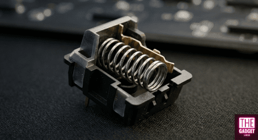
When considering how long does a mechanical keyboard last, we must analyze the fatigue of the high-carbon steel springs inside switches that manufacturers rate for 50 million to 100 million keystrokes.
The foundational mechanism of the mechanical switch is the compression spring, usually fabricated from high-carbon steel, stainless steel, or specialized copper alloys. The longevity of this component is defined by its ability to store and release mechanical energy repeatedly without exceeding its elastic limit. According to Hooke’s Law, the force exerted by the spring is F = −kx, where k is the spring constant and x is the displacement from equilibrium.
Elastic Limits and Plastic Deformation
Every spring possesses a definitive elastic limit, representing the maximum stress the material can endure before the atomic structure is permanently altered. In mechanical keyboard switches, the design goal is to ensure that even at a full “bottom-out” (typically 4.0mm of travel), the internal stress remains well within the linear elastic region of the material’s stress-strain curve. If a spring is over-compressed or has manufacturing defects, it may undergo work hardening, in which local dislocations in the metallic crystal lattice make the material more brittle and prone to early failure.
Over millions of cycles, even springs operating within their nominal limits are susceptible to fatigue. This process involves the nucleation of microscopic cracks at points of local stress concentration or surface imperfections. Under cyclic loading, these cracks propagate slowly across the wire’s cross-section. This is often observed as a gradual reduction in the spring constant before ultimate failure, a phenomenon where the key feels “lighter” or loses its snappy return. Heat treatment is critical here; a properly annealed spring exhibits a more uniform molecular structure, allowing it to absorb stress evenly and resist the crack growth that underpins the 50-million to 100-million keystroke ratings quoted for premium switches.
Molecular Fatigue in Elastomeric Domes
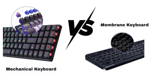
When comparing different technologies to see how long does a keyboard last, the Mechanical vs. Membrane debate is crucial. While a mechanical switch can handle millions of cycles thanks to energy elasticity, a membrane board’s lifespan is limited by the entropic decay of its polymer chains.
In contrast to the energy elasticity of metal springs, rubber dome and membrane keyboards rely on the entropic elasticity of polymers. When an elastomer dome is depressed, the long-chain polymer molecules are forced from their high-entropy, random-coil state into a more ordered, low-entropy arrangement. The “return” of the key is essentially the polymer chains seeking to regain their disordered state.
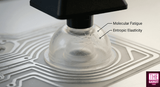
The failure mode for these systems is fundamentally different. Elastomers are prone to molecular fatigue, where repeated deformation breaks the crosslink points between polymer chains. As crosslink density decreases, the material’s elastic modulus drops, leading to the “mushy” sensation characteristic of aged membrane boards. Ageing adds to this: oxidation, heat, and — for elastomers left exposed — UV and ozone can drive further chain scission or crosslinking, eventually leaving the dome brittle enough to crack or too soft to return the keycap.
How long does a keyboard last: Mechanical vs. Membrane
| Actuation Technology | Primary Material | Elastic Mechanism | Typical MTBF (Keystrokes) |
| Mechanical (Linear/Tactile) | High-Carbon Steel | Energy Elasticity (Atomic Distance) | 50M – 100M |
| Hall Effect (Magnetic) | Stainless Steel | Energy Elasticity (No Contact) | 100M+ |
| Membrane (Rubber Dome) | Silicone/Nitrile | Entropic Elasticity (Chain Order) | 5M – 10M |
| Scissor Switch | Silicone + Plastic | Hybrid (Entropic + Lever) | 10M – 30M |
Hall Effect Reliability: The Contactless Frontier and Sensor Drift
The most significant shift in keyboard engineering is the move toward Hall Effect (HE) magnetic sensing, a transition that has fundamentally redefined the benchmarks for how long does a keyboard last. By eliminating the physical contact leaf, HE switches remove the primary mechanical failure modes of oxidation and contact fatigue. That is why manufacturers rate these gaming-grade sensors at 100 million keystrokes and above — a rating, it should be said, rather than an independently measured result.
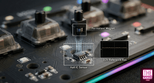
However, this ‘contactless’ advantage introduces a new class of electronic failure modes, such as sensor drift, centered on the stability of the magnetic field and the sensor’s voltage reference.
Magnetic Flux and the 3.2V Reference Rail
Hall Effect sensors operate by measuring the Hall voltage (V_H), generated when a magnetic field (B) passes through a semiconductor carrying a current (I): V_H = R_H × I × B ÷ t, where R_H is the Hall coefficient and t is the thickness of the sensing element. In a keyboard, the precision of the actuation point depends heavily on the stability of the analog-to-digital converter (ADC) reference voltage — in practice, the same low-voltage rail that feeds the microcontroller.
“Ghosting” in a magnetic context is not just a matrix issue but a signal integrity problem. If the battery sags or the reference voltage fluctuates due to high MCU load, the sensor may misinterpret the magnetic flux density, leading to unintended inputs or “drifting” actuation points.
High-performance boards running at 8000Hz polling rates exacerbate this by drawing significant burst current, which can induce noise on the reference rail if the PCB decoupling is inadequate.
Thermal Equilibrium and Non-Linear Drift
Sensor drift is the primary “wear” factor in HE keyboards. Unlike a mechanical switch that either works or chatters, an HE switch can slowly change its behavior based on its thermal environment. As temperature increases, the strength of the permanent magnet in the switch stem decreases. Simultaneously, the semiconductor sensor’s sensitivity shifts.
Both effects are reversible, but on a switch whose actuation point is specified in tenths of a millimetre, they are enough to move where the key registers. No independent bench measurement of that shift on a consumer keyboard has been published, so any precise millimetre-per-degree figure should be treated as unverified. The practical consequence, though, is not in dispute: calibrate the board at the temperature you actually use it at. Calibrating a cold board can leave you with a profile that feels mushy or hypersensitive once the case, the LEDs, and the MCU have warmed up through a long session.
| Drift Parameter | Observation | Technical Root Cause |
| Temperature Shift | ±0.05mm per 10°C | Magnet strength vs. Temperature (Curie-related flux loss) |
| EMI Interference | Stochastic Jitter | Signal noise from unshielded PC components/routers |
| Zero-Point Drift | Mushy feel | Aging of the Hall IC semiconductor material |
| Reference Sag | Ghosting/Missed Keys | 3.2V rail instability under 8K polling load |
Tribology of Polymers: Friction, Wear, and Material Selection
The “feel” of a switch over time—its scratchiness or smoothness is a matter of tribology, specifically the interaction between the moving stem and the fixed housing. The industry has moved beyond basic plastics to high-performance engineering thermoplastics like Polyoxymethylene (POM), Polycarbonate (PC), and Ultra-High-Molecular-Weight Polyethylene (UHMWPE).
Friction Coefficients and Self-Lubrication
POM has long been the gold standard for stems because it is an engineering thermoplastic that pairs low sliding friction with high wear resistance and tight dimensional stability. However, the quest for “butter-smooth” switches has led to the adoption of UHMWPE and blended materials like “LY.” UHMWPE carries a coefficient of friction of roughly 0.10 to 0.20 — the lowest of any unfilled thermoplastic — but it is a softer material that can deform under the stress of friction-fitted keycaps, leading to increased wobble over time.
Material Synergies and the “Thock” Factor
The interaction of these materials also dictates the acoustic longevity of the keyboard. Nylon (PA66) is often preferred for housings because it is denser and provides a deeper sound profile, while Polycarbonate is used for transparent housings due to its clarity and higher pitch. A failure mode often overlooked is “switch creep,” where the repeated thermal expansion and contraction of the housing (catalyzed by high LED heat) causes the switch to lose its secure fit in the plate or PCB.
| Polymer | Hardness (Shore D) | μk (Friction) | Elastic Modulus (GPa) | Characteristic |
| POM | 88 | 0.25 | 2.50 | Balanced, self-lubricating |
| Nylon (PA66) | 70 | 0.28 | 2.30 | Tough, muted sound |
| PC | 93 | 0.31 | 2.35 | Rigid, clear, high-pitched |
| UHMWPE | 60-65 | 0.02 | 0.7-1.0 | Ultra-smooth, prone to deformation |
Surface Chemistry: The Degradation of Keycaps and Coatings
The interface between the user and the machine is where chemical failure modes dominate. The two primary materials, ABS and PBT, represent a trade-off between manufacturing ease and long-term stability.
UV Scission and the Yellowing of ABS
Acrylonitrile Butadiene Styrene (ABS) is a terpolymer where the butadiene component provides impact resistance but is highly susceptible to photo-oxidation. When UV radiation strikes the polymer, it initiates “chain scission,” breaking the molecular bonds and leading to yellowing and surface brittleness. This is more than an aesthetic issue; as the surface becomes brittle, it develops micro-cracks that can eventually lead to the failure of the keycap’s mounting stem.
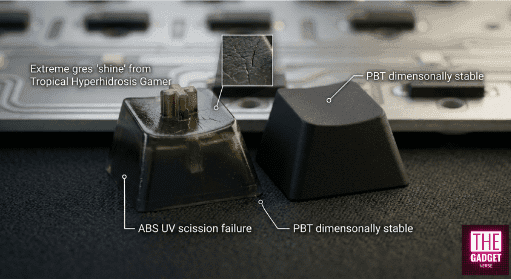
PBT, a semi-crystalline polyester, offers much higher resistance to UV and chemical solvents. Its shine resistance is structural rather than thermal: PBT’s chains pack into ordered crystalline regions while ABS stays amorphous, so PBT does not polish itself smooth under a fingertip the way ABS does. Those same crystalline regions give PBT a melting point near 220°C against roughly 105°C for ABS, plus better wear resistance and low moisture uptake. Even PBT, however, is not immune to hydrolysis if exposed to hot, humid environments for extended periods.
The Tropical Hyperhidrosis Model and Solvent Crazing
The worst case for a peripheral’s surface is hot, humid, and sweaty: high ambient temperature, high relative humidity, and long hours of skin contact. In that environment, sweat and skin oils act as a mild solvent, accelerating the migration of plasticizers out of soft-touch coatings. Left long enough, the coating stops behaving like a coating at all and degrades into a dark, tacky residue. Note that this is a coated-surface failure — soft-touch shells, rubberized wrist rests, coated caps — not something bare ABS or PBT does.
Cleaning solvents cause the other common surface failure. High-purity Isopropyl Alcohol (IPA) is a known cause of “crazing” — a network of thousands of micro-fractures — in stressed amorphous plastics, particularly ABS and Polycarbonate. The alcohol penetrates between the polymer chains and lets the part crack under its own moulded-in internal stress. The safer default is ordinary 70% IPA rather than 99%: the added water slows evaporation and blunts the solvent attack. Whichever you use, test it on an inconspicuous surface first.
Electronic Oxidation and the Logic of Debouncing
For traditional mechanical switches, the most common electronic failure is contact oxidation. When copper-based contacts are exposed to moisture, they form non-conductive oxides that interfere with the low-voltage signals used to register keypresses.
Contact Leaf Chatter
“Chatter” is the registration of multiple inputs from a single physical press. While this can be caused by dust or debris, it is often a result of metal fatigue in the contact leaf. As the leaf loses its springiness, the duration of its “bounce” increases. Firmware like QMK or ZMK handles this through debounce algorithms, which can be categorized as “Eager” or “Defer”.
- Eager Debouncing: Reports the keypress immediately on the first contact and ignores further signals for the duration of the debounce window (typically 2ms–5ms). This is preferred for gaming, but it can register false inputs if the switch is failing.
- Defer Debouncing: Waits for the signal to remain stable for the entire window before reporting. This is safer but adds deterministic lag.
For an aging keyboard, increasing the debounce time to 10ms or more can extend its functional life, albeit at the cost of responsiveness.
Signal Processing and 8K Polling Bottlenecks
Modern 8000Hz keyboards present a unique failure mode related to Interrupt Request (IRQ) resources. Processing 8,000 packets per second consumes significant CPU overhead. If the system is not optimized or uses a front-panel USB header with poor shielding, the result is “packet jitter,” where the ultra-low latency advantage is lost to signal instability. Furthermore, the thermal stress of high-speed MCU processing can lead to solder joint fatigue over the years of use, especially around the high-density pins of the controller IC.
Biomechanical Factors and Research-Grade Measurement
The longevity of a keyboard is also a function of the typist. Instrumented-keyboard research at the University of Michigan’s Center for Ergonomics measured how hard people actually hit keys, and the answer is: far harder than the switch needs. Averaged peak reaction forces during typing came out at 2.54 N — 5.4 times the 0.47 N make force of the switch being used — ranging from 3.33 N under the thumb down to 1.84 N under the little finger (Martin et al., Human Factors, 1996).
Impact of Strike Force on MSS
Heavy typists who consistently “bottom out” against the mounting plate not only accelerate the wear on the switch’s internal dampeners but are also associated with a higher risk of Musculoskeletal Symptoms (MSS).
Mechanical switches with a tactile bump (like “Browns”) or a click (like “Blues”) provide a “bio-feedback” mechanism that can train a user to release the key early, potentially extending both the life of the switch and the health of the user’s tendons.
Ergonomic Implications of Actuation Depth
Hall Effect switches allow for adjustable actuation points, which can be used as an ergonomic tool. A higher actuation point (e.g., 1.0mm) can reduce the total travel required, potentially lowering finger fatigue during high-intensity sessions. However, this requires a more stable sensor environment to avoid “mis-triggers” caused by the aforementioned thermal drift.
Manufacturing Precision: CNC Aluminum vs. Injection Molding
The structural lifespan and acoustic consistency of a keyboard are dictated by manufacturing tolerances. A premium keyboard is often defined by its “gap consistency”.
Tolerance Profiles and Mold Wear
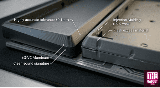
CNC-machined aluminum cases, typical of high-end custom boards, are generally quoted at tolerances on the order of ±0.1mm, with case gaps in the 0.3mm to 0.5mm range.
This precision ensures that the acoustic resonance of the case remains consistent over time. In contrast, injection-molded plastic cases exhibit wider gaps (0.5mm to 0.8mm) and are subject to mold wear. As a mold reaches the end of its lifecycle, parts may exhibit more “flash” or “sink marks,” leading to poor fitment and increased rattling as the keyboard ages.
| Manufacturing Method | Target Gap (mm) | Tolerance Limit | Failure Mode |
| CNC Aluminum | 0.3 – 0.5 | ±0.1mm | Anodization warping/Stripped threads |
| Injection Molding | 0.5 – 0.8 | ±0.2mm | Thermal contraction/Sink marks |
| 3D Printing (SLA) | 0.4 – 0.6 | ±0.1mm | UV degradation/Brittleness |
The Regulatory Horizon: Anti-Obsolescence and Right to Repair
The legal landscape around keyboard longevity has already shifted, and not where most coverage says it has. The Anti-Obsolescence Act is Québec provincial law — Bill 29, passed in 2023 — and its warranty of availability of replacement parts, repair services, and repair information came into force on 5 October 2025. It is Canadian, not American. On the US side, California’s Right to Repair Act took effect on 1 July 2024, and Colorado’s Consumer Right to Repair Digital Electronic Equipment law (HB24-1121) followed on 1 January 2026. A federal Fair Repair Act was reintroduced in Congress in February 2026 but has not passed.
Impact on Keyboard Architecture
These laws specifically target “parts pairing” and software restrictions that “lock in” customers. What they actually require is that manufacturers make parts, tools, and documentation available on fair and reasonable terms — not that every component be sold individually, so no manufacturer is compelled to stock loose switches or daughterboards. Coverage is narrower than the headlines suggest, too: Colorado’s version exempts several equipment categories outright. The realistic effect on the keyboard industry is steady pressure toward modular designs and away from genuinely disposable ones, measured in years rather than product cycles. From a longevity perspective, that shifts the limiting factor away from a board’s most fragile component and toward the owner’s willingness to perform maintenance and replace modular parts.
Synthesized Conclusions on Functional Lifespan
To conclude, the answer to how long does a keyboard last isn’t just a number; it is a managed decay of several variables, like spring elasticity and sensor drift. In service terms, a high-quality mechanical keyboard is commonly put at a 10-to-15-year investment, provided that the user understands the interplay between material science and electronic maintenance.
The transition to Hall Effect technology removes the 100-million-click “hard cap” of metal fatigue but introduces the subtle, non-linear challenge of sensor drift and thermal management. Meanwhile, the choice of plastics like PBT and the avoidance of aggressive solvents like 99% IPA are the primary defenses against the chemical breakdown of the physical interface.
Ultimately, the most durable keyboard of the next decade will be one that combines a contactless HE sensing array with a modular, CNC-machined chassis, PBT surfaces, and firmware that complies with the emerging “Right to Repair” standards allowing the user to bypass planned obsolescence and maintain the device at peak technical performance for a generation of use.